
To perform his survey, the marine surveyor has a vast array of tools and equipment that he may use depending on the task to accomplish.
1- Visual examination:
As it may appear simplistic, the visual examination is the first action the marine expert has to do. This will allow him to get a first general overview of the boat he has to survey. This first overview will give him many inputs:
- Degradation, lack of maintenance, or pristine condition despite the old age of the boat…
- Simple tools such as a head lamp, a series of magnifying lenses, a digital video camera as well as a good numeric photo camera that will allow professional quality pictures, a small mirror possibly mounted on a flexible rod are valuable tools that you should find in the tool box of a competent marine surveyor.
- In some cases, an endoscope with a connection to a digital camera will be very useful in some areas difficult to reach.
2- Acoustic tests:
Regularly used during surveys on wooden or composite hulls, right after the visual examination, a series of acoustic tests may occur. In its most simplistic way, an acoustic test is made with light impacts done on the hull surface with a hard object, possibly a small hammer. The sound emitted by the material in response to the impact will give a lot of information. Generally, the sound resulting from the impact should be light and clear. In the areas made of humid wood, fiberglass, or delaminated composite, the resulting sound will be very different. This simple test will allow identifying various areas of the hull and deck that need to be investigated further with modern instruments such as a humidity tester for example. Hulls built in sandwich GRP will be more difficult to diagnose as the core foam material will act as sound insulation and may alter the results of the acoustic test.
3- Ultrasonic tests:
Sophisticated instruments allow to measure the thickness of a metal hull built in steel or aluminum. Other instruments will allow to sound the hulls or other structural elements made in composites. These instruments induct a sound wave into the material that will propagate. The echo of this signal will be captured by the instrument and analyzed. If we know the speed at which the signal travels into a specific material, then the instrument will be able to calculate the distance between the surface of the material and the echo’s origin. All these sophisticated instruments must be calibrated in the function of the tested material. For example, the speed of propagation of the sound is different in steel compared to aluminum or a composite made of carbon/epoxy. This method also allows to detect cracks in welded areas or to evaluate the integrity of structural elements made of composites. With this technology, we can also measure the thickness of an old metal hull that can be attacked by corrosion. During the survey of a hull made of steel, we measure the thickness of the hull in various locations and produce cartography of the hull describing the thickness of the various selected points. If the hull is attacked by corrosion, the thickness of the hull will be reduced. If the thickness is reduced by less than 20%, we consider that the hull is sound. If we find areas with a thickness reduction of more than 20%, we replace them with new steel plates.

4- Radiography:
This technology is used for the inspection of welded areas and cast parts. Today, this technology can also be used on composites parts or other materials that require in-depth inspection, which means way below the material’s surface. This technology works on the absorption difference between two-parent materials and the possible presence of inclusion defects in the tested part. Such problems as cracks, crevasses, or other defects absorb less radiation compared to the main material. Consequently, it appears on the radiography picture shadow areas that are darker indicating defects in the material. It is the same principle as the radiologist diagnosing a bone fracture. This technology allows the diagnosis of defects in complex structural components. Radiography is used to inspect keel bolts and nuts. The radiation does not go through lead ballast. However, it goes through large thicknesses of wood and GRP. It is then possible to detect the corrosion level of the bolts and nuts as well as the possible presence of cracks in them. However, the propagation of X-rays, Cobalt 64, and Iridium 192 are dangerous for human health. If you use this technology, you need to be very careful and protect yourself from radiation. Radiography of parts made in composite materials is also possible.


Magnetic Particles Inspection (MPI) :
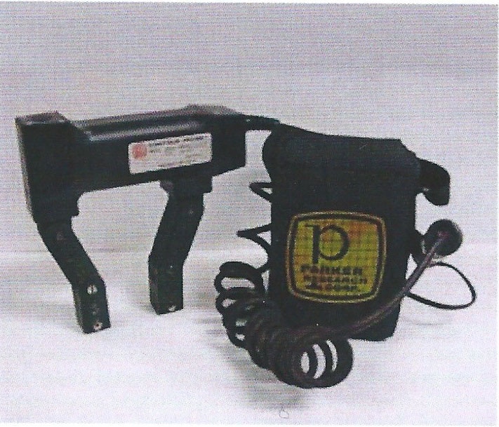
This method allows to find surface defects and also defects present at low depth in the tested material. This technology only works on ferrous material such as steel. A powerful magnet is placed in the area of the tested part. In most cases, we use an electromagnet. This allows to activate and deactivate the magnet on demand. It also can be positioned in the function of the size and geometry of the tested part. A magnetic flux is propagating between the two magnet poles. A discontinuity into the material (a crack for instance) will cause a leak of the magnetic flux. Small vaporization of magnetic particles is applied on the surface of the tested part. These particles will be attracted in the areas where the magnetic flux leak is located. This is how we detect the presence of cracks in the material using this technology.
Magnetic Particles Inspection 1
Lines of “magnetic flux” flow between the two poles of the magnet. Discontinuities between the poles will cause a leakage of the flux from the metal surface. A suspension of fone magnetic particles is prayed onto the surface ans these particles will be attracted to the leaking flux

Magnetic Particles Inspection 2
Lines of “magnetic flux” flow between the two poles of the magnet. Discontinuities between the poles will cause a leakage of the flux from the metal surface. A suspension of fone magnetic particles is prayed onto the surface ans these particles will be attracted to the leaking flux
Magnetic Particles Inspection
Cracks in a plastic casing show-up clearly with dye penetrant and developer

Magnetic Particles Inspection 3
Lines of “magnetic flux” flow between the two poles of the magnet. Discontinuities between the poles will cause a leakage of the flux from the metal surface. A suspension of fone magnetic particles is prayed onto the surface ans these particles will be attracted to the leaking flux
International Institute of Marine Surveyors.
http://energyworkforces.net/?p=107
http://www.mr-chemie.de/en/products/magnetic_particle_testing/
http://www.mr-chemie.de/en/products/magnetic_particle_testing/
IIMS, International Institute of Marine Surveyors.
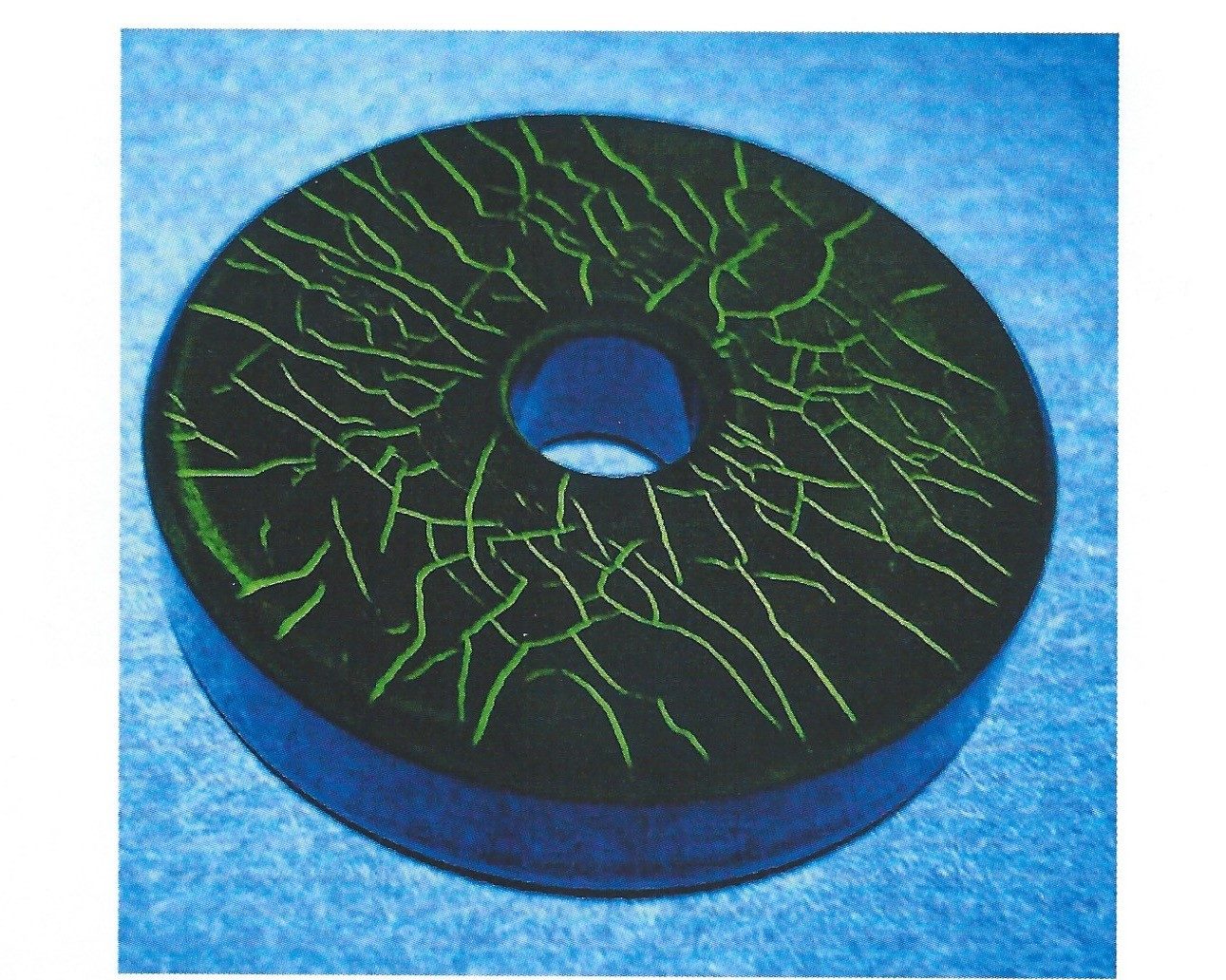
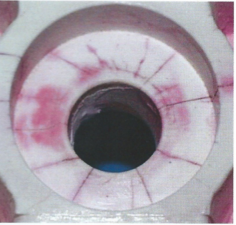
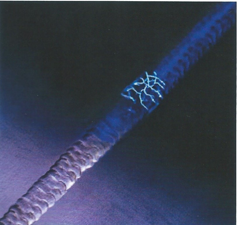
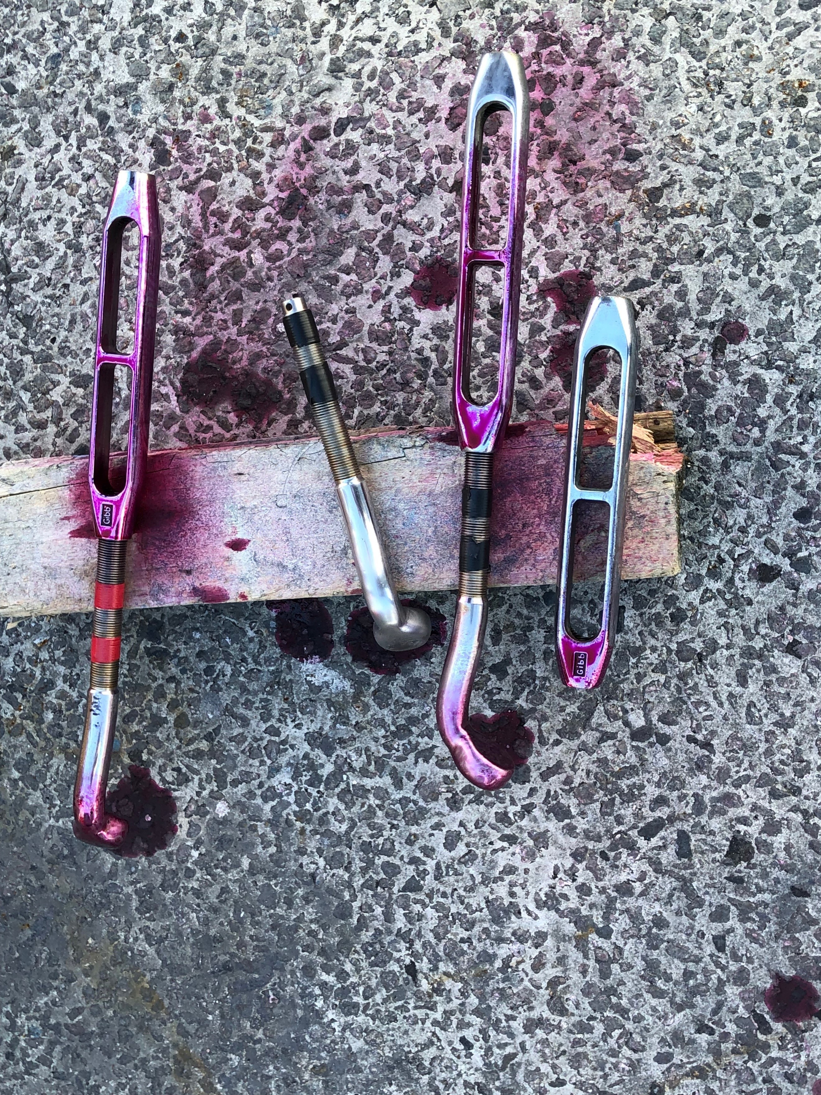
6- Dye Penetrant Inspection: This method is limited to find defects present only at the surface of the tested materials. This method works on all types of metals and also on composites. The surface that is inspected must be clean. We often use a solvent to clean the part and make sure it is free of grease, oil, corrosion, or dirt. A low viscosity penetrant liquid is applied o the surface of the tested part. We allow a specific time for the penetrant liquid to penetrate into the material. The capillarity phenomenon will allow the penetrant liquid to go inside the material through any present small cracks or defects. The excess penetrant product is then removed. Then, a small coat of talc is vaporized on the surface. If we use a fluorescent penetrant liquid, we use ultraviolet as a developer. All the defects such as the cracks appear on the surface under the ultraviolet light. The penetrant liquid will shine in the dark. This method is largely used for mast and standing rig inspections. The stressed areas by fatigue are easily located.
Dye Penetrant Inspection: 1
Cracks in a plastic casing show-up clearly with dye penetrant and developer
Dye Penetrant Inspection: 2
Using UV light and a fluorescent dye surface cracks in a weld glow agaist the backgroung
Dye Penetrant Inspection 3
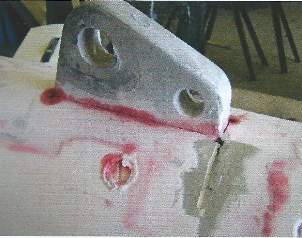
Dye penetrant and developer being used to check for cracks around a mast forestay fitting
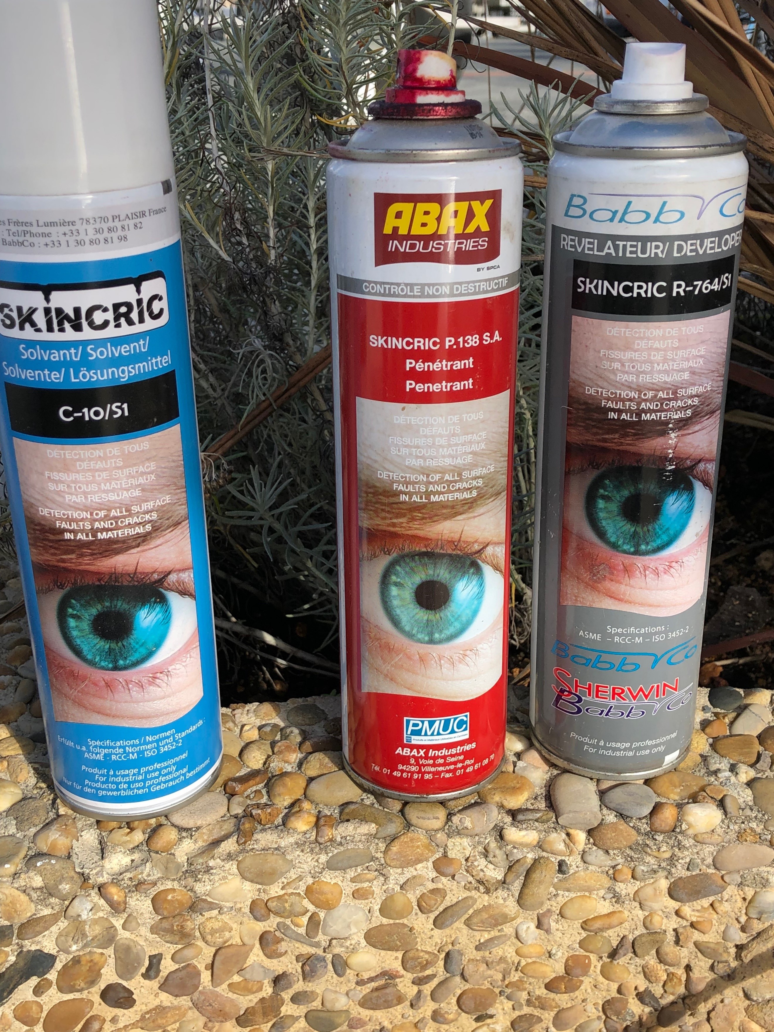
Products
Products used during a Dye Penetrant Inspection.
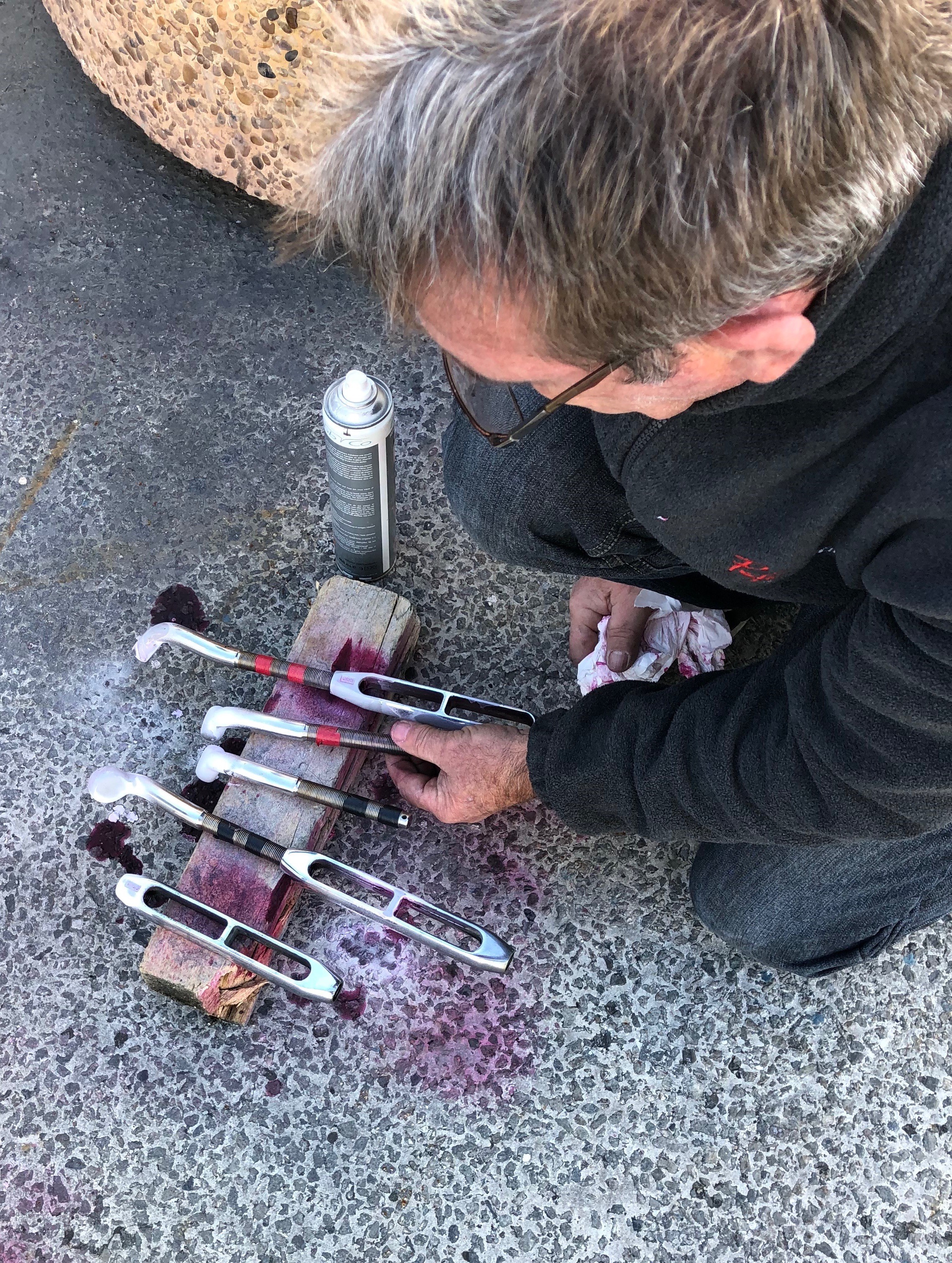
Inspection
rigging components inspection.
rigging components inspection.
7- Thermal imaging:
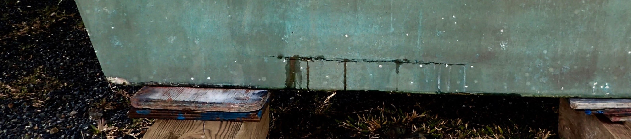
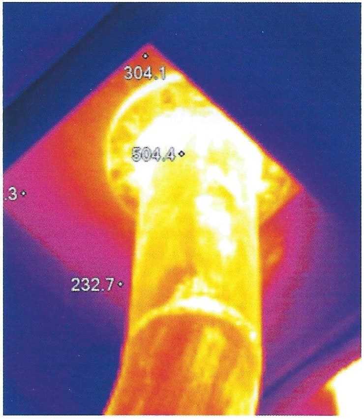
This new technology is growing fast within the community of marine surveyors. The cost of acquiring these thermal imaging cameras is going down and the training costs are also getting more affordable. Thermal imaging technology allows to see what the human eye can’t. A thermal imaging camera will allow you to see the thermal radiation coming from different materials or systems that may be potentially defective. When a system is overheating because of a problem – for instance, an electric control box in which a wire gets too much amperage or an electric motor that is not well maintained and therefore is overheating – it is then possible with this technology to detect the area of the system that does not operate well. For the same reason, a delaminated area of a GRP hull that will absorb seawater will show a temperature that is different compared to the sound parts of the same hull. Under the effect of solar radiation, this GRP hull is going to heat and the humid areas of this hull will show a different temperature compared to the sound areas. An image worth a thousand words!
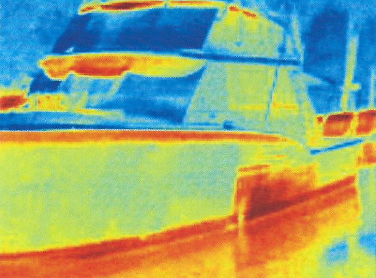
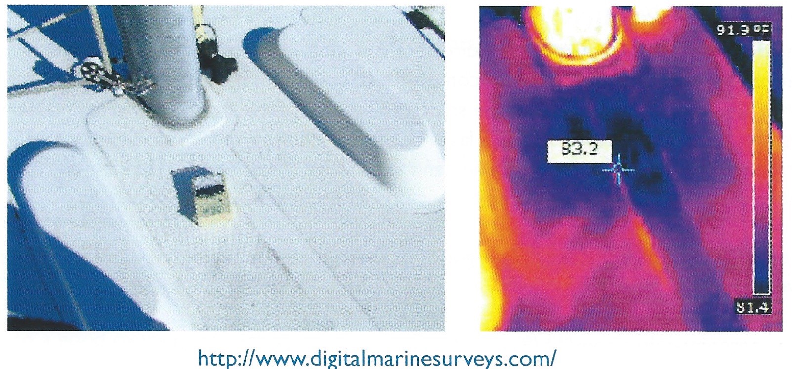
The deck is delaminated in front of the mast and the dark zone shows it. The balsa core has absorbed humidity which is confirmed by the humidity tester and the thermal imaging camera.
8- Humidity testers:
This technology is widely used by marine surveyors as it allows to detect a major problem found in GRP: Osmosis. But with the same instrument, you can also measure humidity in wooden hulls. You can inspect planking, frames as well as any wooden structural part. The rot that may attack any wooden structure always starts with a humidity saturation stage. Being able to detect this phenomenon early gives you an advantage as it reduces the cost of repair and preserves the structural integrity of a wooden hull. The humidity meters that work by measuring the impedance are the most sophisticated ones. They don’t damage the surface of the hull when you test it. This is not the case of “Pin meters” which leave visible marks on the surface. The humidity testers that work by impedance are equipped with electrodes that transmit a frequency signal into the material this instrument measures the impedance (magnetic resistance) and convert this measure into a level of humidity.
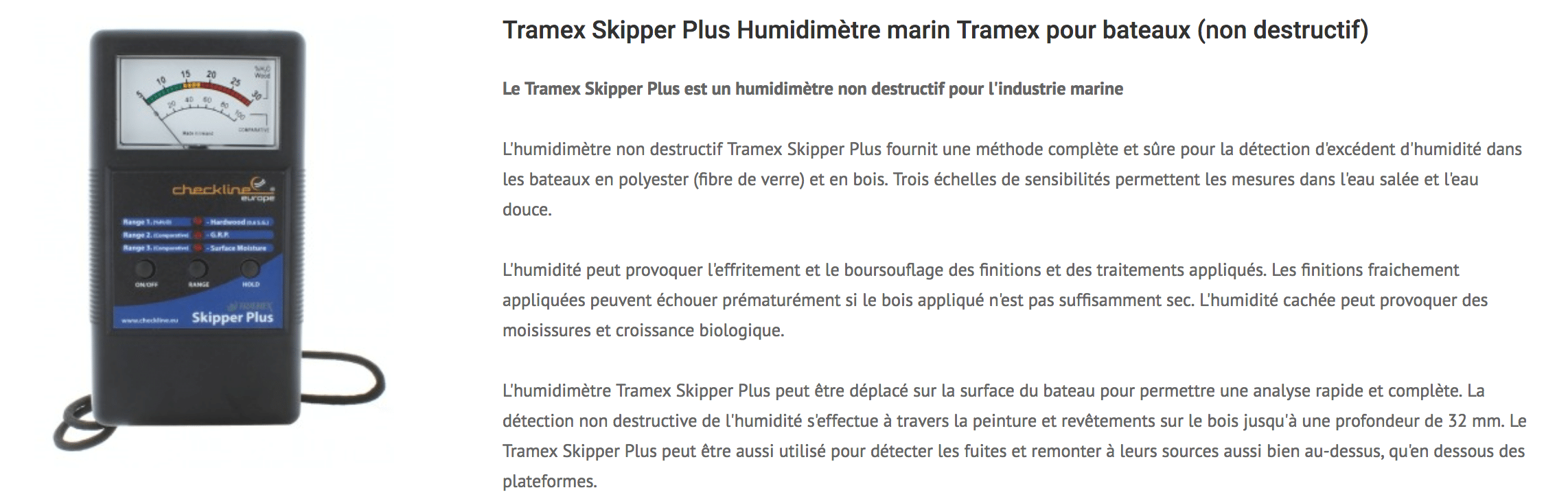
Source : Tramex.
It is important to understand that training is capital for using adequately these instruments. You just can’t improvise yourself as an expert… To make sure you are using these instruments adequately, you must work on dry and clean hulls, specially at the keel level. Take humidity measurement on a boat that was just pulled out of the water is useless…